Clip Volumes
Clip volumes are elements that limit the display of a view to the region within the constraints of the clipping element. When a clip volume is applied, only the elements within the clip volume are used for that view.
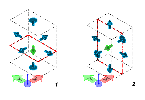
Two clip volumes are shown here. (1) A clip volume to create a plan section. (2) A clip volume to create an elevation section. The cutting plane displays in red.
Clip volumes can consist of any solid (other than spheres or feature solids), and any closed surface extrusion or cylinder.
This is how the clip volume works:
- A clip volume is generated by sweeping a planar element (cutting plane) through a model.
- Clip volumes produce section graphics along the cut plane. Section graphics are the lines, arcs, and curves that display in the view when a clip volume (cutting plane) passes through the Building components.
- The clip volume encloses a space containing a cutting plane that passes through. Section graphics are produced by the cutting plane and this is called the Cut.
- Building components inside the clip volume, behind the cutting plane, are in the Back or Reflected view.
- Building components that are in front of the cutting plane are in the Forward view.
- The display of geometry can be controlled by settings in the View Attributes dialog, Building panel, General tab.